B-9. Motor Drive 3-Phase-Modulation Po=10kW

Add a bio to your profile to share information about yourself with other SystemVision users.

Member of the PartQuest Explore Development Team. Focused on modeling and simulation of analog, mixed-signal and multi-discipline systems covering a broad range of applications, including power electronics, controls and mechatronic systems.

Add a bio to your profile to share information about yourself with other SystemVision users.
Electric Power Steering (EPS) systems provide a challenging control design problem for system integrators. Because the system directly interacts with the driver’s hands, reducing vibration is a must. But controlling the system’s fundamental mechanical resonance requires loop compensation, such as lead, which can make the system sensitive to higher frequency disturbances (1). This can include cogging and torque ripple from the motor, or commutation noise from the drive electronics. For this reason, it is essential to have a tool flow that supports a coordinated design effort across these technologies.
Figure 1. EPS System with Ideal PMSM and Drive
Note: This is a "tunable" design. Many of the system parameters can be changed by the user. Then a new simulation can be run and the updated results can be observed in the waveform viewers. Changable parameters are shown in blue, you many need to zoom in to see them clearly.
Figure 1 shows an EPS System design that includes an ideal Permanent Magnet Synchronous Machine (PMSM) model, as well as a continuous D-Q controller and drive circuit. The mechanical load model includes static and kinetic friction, a steering force that varies with rack displacement, as well as various mass, inertia, damping and spring/stiffness elements of the steering system. The steering torque, applied by the vehicle's driver, is assisted by torque from the motor scaled by the gear ratio. For the control, a non-linear gain profile is specified in the "torque_assist_table" function, and a lead-lag compensator is used to improve system stability.
The simulation results indicate a relatively smooth response to a sinusoidal steering wheel angle change of 90 degrees peak-to-peak, over a 1 second time interval. Note in particular, in the upper right graph, that the assist torque (red waveform) is approximately 3x the driver’s applied steering torque (blue waveform), with little vibration except at transitions through the zero commanded torque dead-band, as specified by the torque-assist profile. Note there is also some initial disturbance due to stick/slip load friction. (You may need to expand the size of the waveform viewer to see the detailed features of these signals)
Once the design is considered acceptable at the conceptual phase, more detailed component design and selection can begin. Very fast and effective motor design can proceed using Simcenter E-Machine Design (formerly Simcenter Motorsolve):
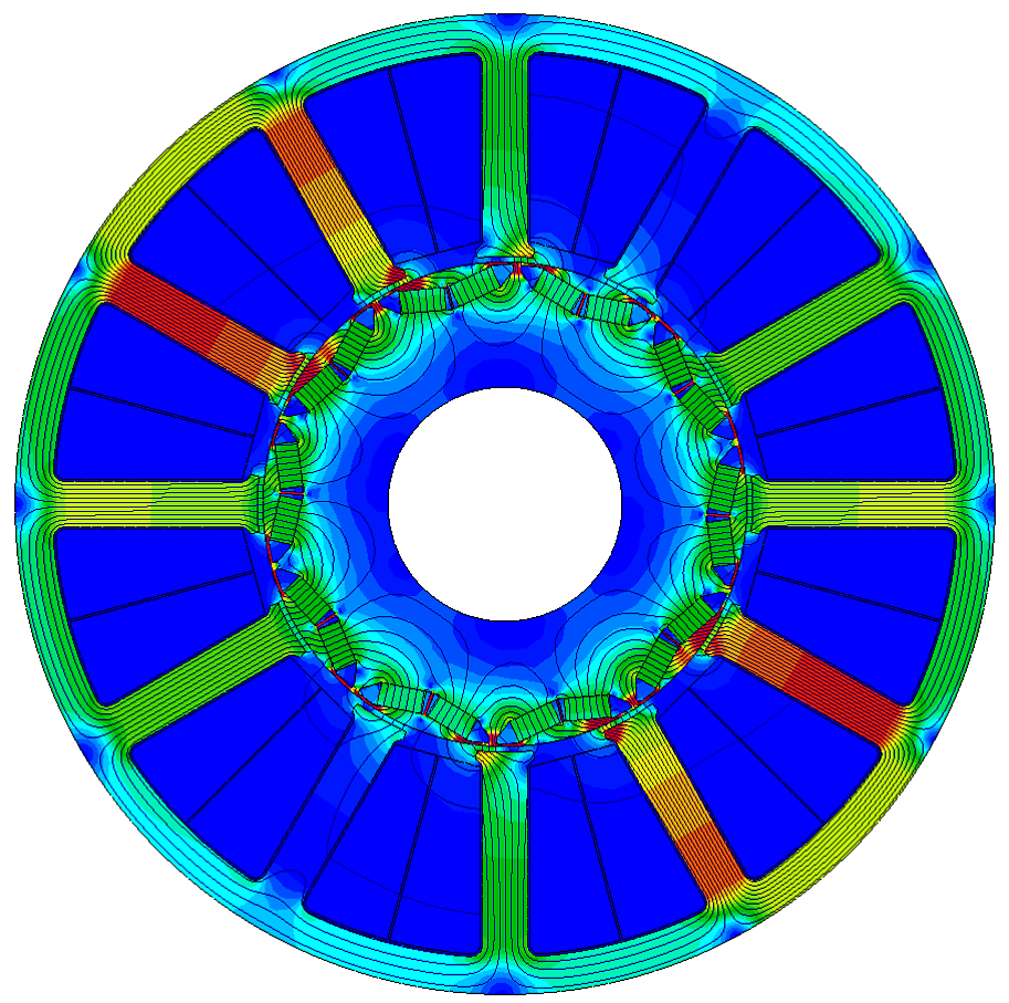
Figure 2. E-Machine Design B-field Analysis of the EPS PMSM Motor
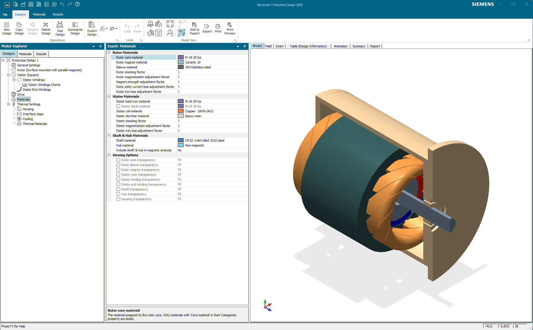 Figure 3. E-Machine Design 3-D rendering of the EPS PMSM Motor
A critically important capability of E-Machine Design for system-level design is that it can export a “1-D” machine model in the IEEE Standard VHDL-AMS format. Those models can therefore be directly imported into PartQuest Explore, for “virtual integration” with the rest of the EPS system, as shown below:
Figure 4. EPS System with high fidelity E-Machine Design generated PMSM model
Note: This design is also “tunable”, you can change parameters in blue and re-run the simulation.
The version of the EPS System design shown in Figure 4 includes the E-Machine Design generated IPM - PMSM motor model. Its behavior includes cogging, saturation, torque ripple and other realistic machine characteristics. The simulation results, especially the red torque assist waveforms, indicates that these parasitic machine characteristics can cause a vibration that may be noticeable to the vehicle driver. Expand the viewer to see the small ripple in the blue torque waveform that is directly applied to the steering wheel.
Figure 5. Full EPS System with high fidelity E-Machine Design PMSM model and DQ/SVM drive electronics
Note: This is a “Live - View” design. You can move waveform probes around and see other signals, but you can't change parameter values.
Finally, in Figure 5, an even higher fidelity EPS System model is shown. This version includes not only the E-Machine Design generated PMSM model, but also a more “physical” representation of the drive electronics. This includes a sampled-data D-Q control algorithm, with space-vector modulation (SVM) to generate digital PWM signals to control the switches of the 3-Phase inverter.
This article illustrates a tool flow, starting with high level (conceptual) modeling and analysis of the integrated system, followed by the physical design and analysis of a suitable machine. Then finally virtual verification of that machine “in-the-loop”, using higher fidelity models of the hardware and control algorithms as their implementation details become available.
---------------------------
(1) D. Lee, K-S Kim and s. Kim, “Controller Design of an Electric Power Steering System”, IEEE Transactions on Control Systems Technology, Vol. 26, No. 2, March 2018
Note: Simcenter E-Machine Design is the next generation of Simcenter Motorsolve
The PartQuest Explore Team is happy to announce that we’re adding many models to support motor and control systems development. We’ve recently added a new PMSM (Permanent Magnet Synchronous Machine) model, and updated our Induction Motor model. We will be adding Stepper and SRM (Switched Reluctance Motor) models in the very near future. Continuous control algorithm blocks that support field oriented control (FOC), such as Clarke and Park transforms, have also been added. Some of these are shown in the design example below.
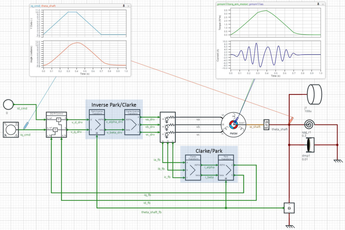
The design schematic shown above represents a PMSM motor driving a simple mechanical load, including a windup spring to test the torque capability of the machine. A continuous FOC block applies ideal sinusoidal phase voltages to the machine. The light-blue waveform, in the left on-schematic viewer, is the quadrature current (Iq) that is commanded for the test. The orange waveform shows the corresponding load shaft angle response. Also, the motor internal torque and phase A current can be observed in the right viewer (green and dark-blue waveforms, respectively).
Click here to explore a “Live” schematic for this design. (Note: Use a Chrome or Firefox Browser for the best experience). You can observe other signals on nets or within any component, and view parameter values. You can also modify and re-simulate a copy of the design to see the effect of those changes. Because the control models are continuous, the simulations run very quickly. So this version is useful for system-level assessment of the overall design performance.
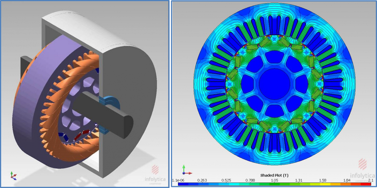
With PartQuest Explore, it is also possible to go deeply into various implementation aspects of the design. For example, using FEA (Finite Element Analysis) software from Infolytica, the physical aspects of the machine (geometry, material properties, winding placements, etc.) can be analyzed and a VHDL-AMS model of the machine generated. Because VHDL-AMS is an IEEE Standard format, this model is completely compatible with PartQuest Explore and can be easily imported, to see how that specific machine will perform in the system.
Likewise, a more detailed assessment of the drive circuit implementation can be made. In the design shown below, the continuous control algorithm has been replaced by an equivalent discrete controller with a 5 kHz sampling interval. The controller also includes an SVM (Space Vector Modulation) algorithm to drive the external three-phase inverter. This version of the inverter uses ideal digitally controlled switches, which receive PWM signals from the controller.
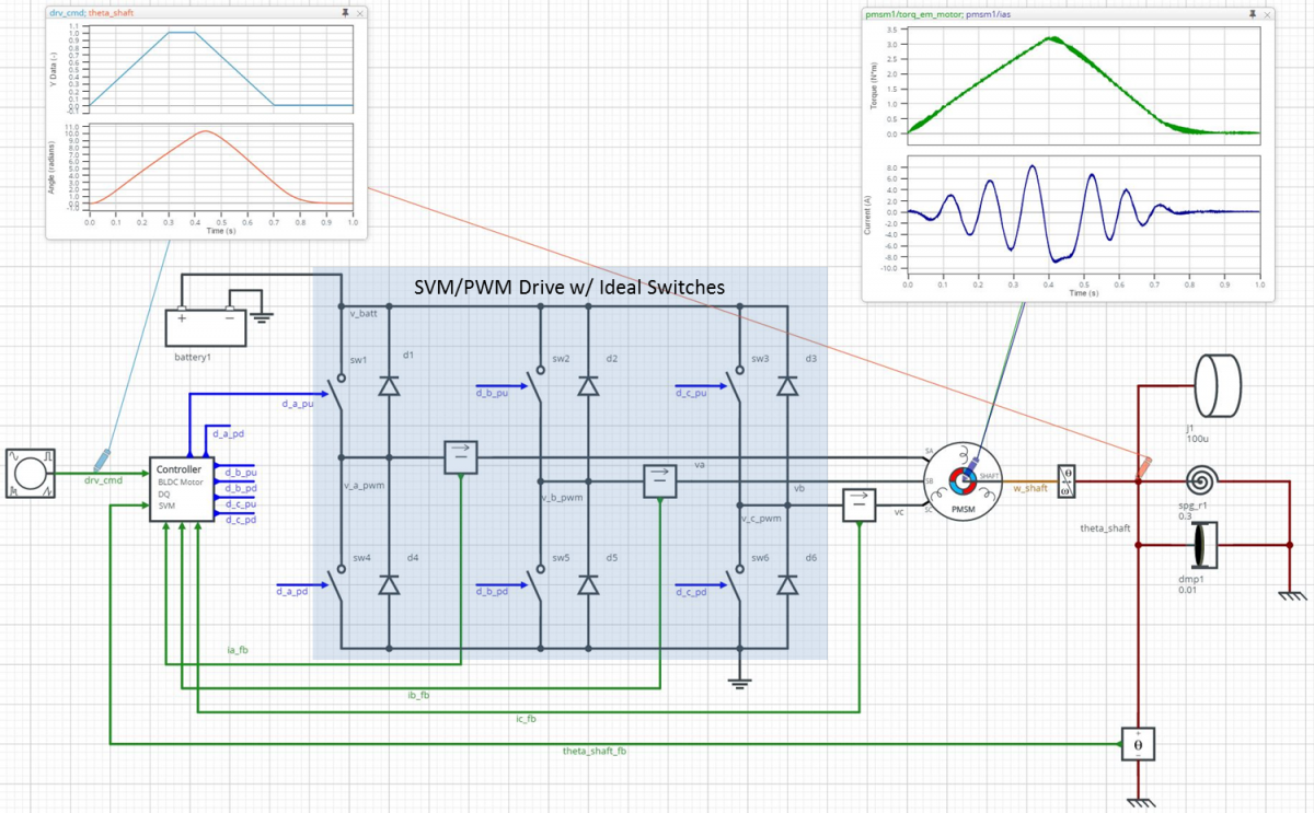
Click here to explore the “Live” schematic for this switching design. It simulates relatively quickly for a switching circuit, but much slower than the continuous version. It is perfect for verifying the discrete implementation of the FOC control, assessing the SVM algorithm, and for selecting an appropriate sample rate.
Finally, in the design below, the ideal switches of the inverter have been replaced by more detailed MOSFET and gate driver models. This version of the design runs even more slowly, so a shorter simulation end-time was used. There is no need to run a complete motion profile, as all of the significant system-level design aspects have already been verified. Rather, this model can help with estimation of switching losses and drive efficiency, evaluate component stress levels and help the designer select properly rated parts.
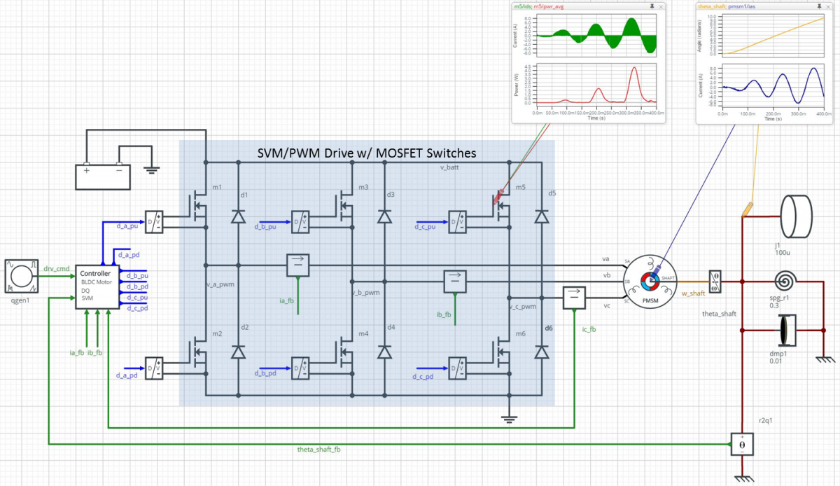
Click here for the “Live” version of the above schematic
The ability to “go deep” as well as to “go high” is a key strength of PartQuest Explore. We think this is of particular value to Mechatronics Engineers, because multi-discipline systems demand the simultaneous assessment of many diverse aspects. This requires the ability to choose the appropriate level of abstraction for each one, depending on the particular goal of the analysis.