by Mike Donnelly
7 October 2016
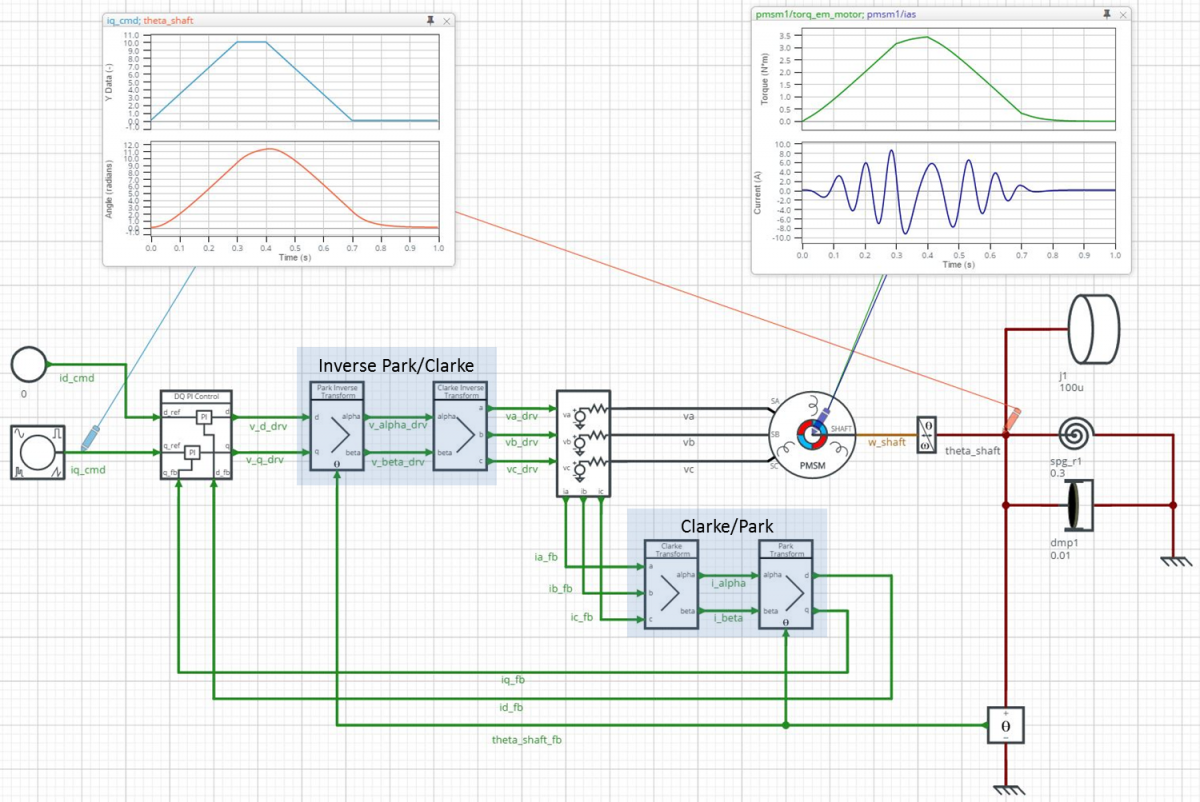
The PartQuest Explore Team is happy to announce that we’re adding many models to support motor and control systems development. We’ve recently added a new PMSM (Permanent Magnet Synchronous Machine) model, and updated our Induction Motor model. We will be adding Stepper and SRM (Switched Reluctance Motor) models in the very near future. Continuous control algorithm blocks that support field oriented control (FOC), such as Clarke and Park transforms, have also been added. Some of these are shown in the design example below.
The design schematic shown above represents a PMSM motor driving a simple mechanical load, including a windup spring to test the torque capability of the machine. A continuous FOC block applies ideal sinusoidal phase voltages to the machine. The light-blue waveform, in the left on-schematic viewer, is the quadrature current (Iq) that is commanded for the test. The orange waveform shows the corresponding load shaft angle response. Also, the motor internal torque and phase A current can be observed in the right viewer (green and dark-blue waveforms, respectively).
Click here to explore a “Live” schematic for this design. (Note: Use a Chrome or Firefox Browser for the best experience). You can observe other signals on nets or within any component, and view parameter values. You can also modify and re-simulate a copy of the design to see the effect of those changes. Because the control models are continuous, the simulations run very quickly. So this version is useful for system-level assessment of the overall design performance.
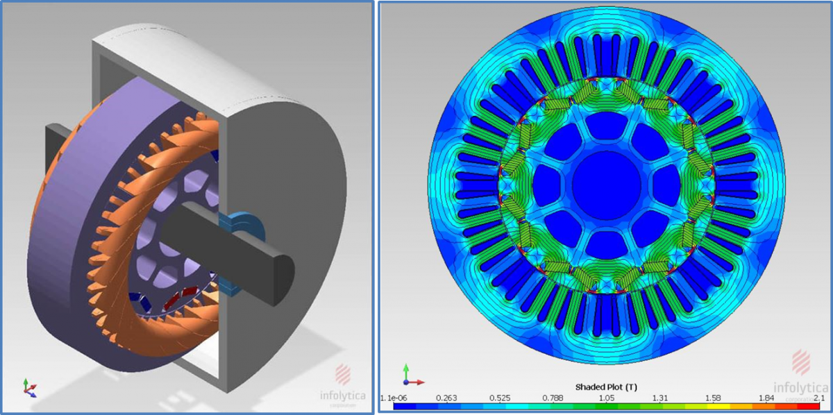
With PartQuest Explore, it is also possible to go deeply into various implementation aspects of the design. For example, using FEA (Finite Element Analysis) software from Infolytica, the physical aspects of the machine (geometry, material properties, winding placements, etc.) can be analyzed and a VHDL-AMS model of the machine generated. Because VHDL-AMS is an IEEE Standard format, this model is completely compatible with PartQuest Explore and can be easily imported, to see how that specific machine will perform in the system.

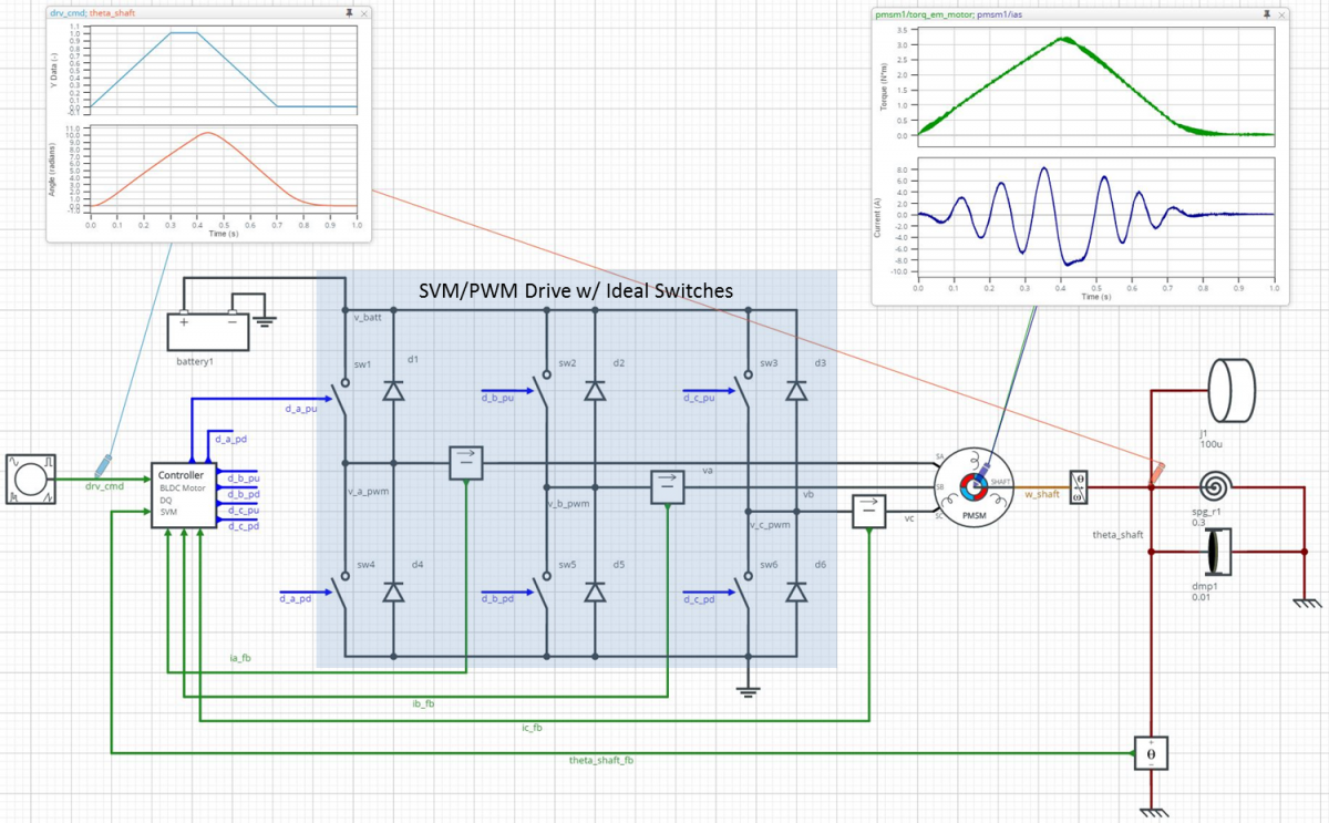
Likewise, a more detailed assessment of the drive circuit implementation can be made. In the design shown below, the continuous control algorithm has been replaced by an equivalent discrete controller with a 5 kHz sampling interval. The controller also includes an SVM (Space Vector Modulation) algorithm to drive the external three-phase inverter. This version of the inverter uses ideal digitally controlled switches, which receive PWM signals from the controller.
Click here to explore the “Live” schematic for this switching design. It simulates relatively quickly for a switching circuit, but much slower than the continuous version. It is perfect for verifying the discrete implementation of the FOC control, assessing the SVM algorithm, and for selecting an appropriate sample rate.
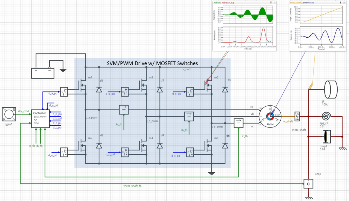
Finally, in the design below, the ideal switches of the inverter have been replaced by more detailed MOSFET and gate driver models. This version of the design runs even more slowly, so a shorter simulation end-time was used. There is no need to run a complete motion profile, as all of the significant system-level design aspects have already been verified. Rather, this model can help with estimation of switching losses and drive efficiency, evaluate component stress levels and help the designer select properly rated parts.
Click here for the “Live” version of the above schematic
The ability to “go deep” as well as to “go high” is a key strength of PartQuest Explore. We think this is of particular value to Mechatronics Engineers, because multi-discipline systems demand the simultaneous assessment of many diverse aspects. This requires the ability to choose the appropriate level of abstraction for each one, depending on the particular goal of the analysis.
- 498 views


