Efficient Solar Battery Charging System

by Mike Donnelly
12 May 2020

Solar energy systems for residential use are typically limited by code to 600V, but commercial installations can operate at higher voltages. This opens the door to more efficient energy utilization. Achieving that efficiency has been made easier with the introduction of Silicon Carbide (SiC) Power Devices from Rohm Semiconductor. These components offer significant performance advantages over their Silicon (Si) counterparts.
Figure 1: Solar Battery Charger System
Rohm has recently provided a large set of SiC power device models in the PartQuest Explore Partner Library. These include MOSFETs, Diodes and Modules. Two of these were used in the power stage of the solar battery charging system design shown in Figure 1. They were key to achieving a 99% steady-state efficiency for this example system. This can be seen in the waveform viewer on the right side of the schematic, which shows the battery input power divided by the output power from the solar panels.
This is obviously not a complete design implementation. It is intended only to help designers assess the performance and energy losses of the hysteresis controlled buck converter power stage. It provides a realistic system context for that stage, including the complex behavior of the source (solar panel), the load (battery), and the control elements that would be needed to support peak power tracking (PPT)* under variable sunlight operating conditions.
Since this is a “Live” design you can change any of the key parameter values (highlighted in blue), and then run a new simulation to see the results of that change. These parameters include:
- Irradiance; sets the sunlight-level operating condition, which affects the power output capability of the solar panel as discussed below
- Panel current (command); sets the target panel current level for the converter
- Gate drive parameters; defines the voltage level, edge-rates (turn-on, turn-off) and driver output resistance that controls the gate of the SiC MOSFET
- Battery voltage; this design can accommodate a wide range of battery voltage levels because of its “current-mode” operation
- Power Diode and MOSFET Selection; Try other parts from the Rohm 1200V SiC component family, to assess their capability and performance in your design configuration
Fun Challenge!
As a challenge, choose a different irradiance level and then try to find the panel current (command) level to maximize battery charging current under those conditions!
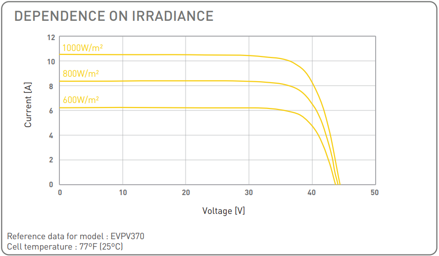
Hint: Figure 2 shows the current vs. voltage dependence on the irradiance level, for the Panasonic EVPV370 solar panel, the type used in our example. Since this graph does not represent a series connection of 22 panels, but rather only 1 panel, the voltage levels are a fraction (1/22) of the panel series in our example. But the currents are not scaled, so the values read from the graph are directly applicable. The maximum power point current is usually just below the “knee” for each irradiance level curve.

Figure 2: Load Current vs. Voltage at different irradiance levels
An even easier method to identify the exact peak power point for the series connected panels is to use the “Live” solar panel calibration test circuit shown in Figure 3. You can just set the irradiance level to the target value and run a new simulation, then move the cursor to the peak of the power waveform and read the corresponding value from the current waveform. To verify this result, just specify that current value and the corresponding irradiance level back in the system design of Figure 1.
Figure 3: Solar Panel Load Test – Maximum Power
Of course if this system’s performance does not meet your application needs, you can click the yellow button labeled “Edit in PartQuest Explore”. You can free-form edit it and save that copy as your own circuit/system design, reusing any part of this one that you like.
The End
- 1303 views
Pagination
- Previous page
- You're on Page 2


