by Mike Donnelly
20 January 2017
Stability is an essential quality of most practical circuits and systems. A traditional stability metric for closed-loop control systems is gain and phase margin, based-on the open-loop transfer function (OLTF) or frequency response. A special physical measurement technique for obtaining the OLTF of an operating closed-loop system, pioneered by Dean Venable* in the 1980s, involves injecting a small sinusoidal stimulus in series with the loop, and measuring the absolute signal levels at the injection site. This is to identify the effective open-loop output-to-input ratio, or the transfer function value, at that particular stimulus frequency. By sweeping the frequency value of the stimulus signal over time, the complete frequency response of the circuit or system under test can be obtained.
Note that this is a “time-domain” measurement (i.e. it is performed in real-life!), that produces a frequency response result. This is just like our TDFS measurement concept, as described in Part 1 of this blog series. A time domain simulation is performed, but the computed results are complex values vs. frequency, just like those of an “AC” or frequency-domain analysis. But traditional “AC” analysis in most simulation environments is applicable only to linear (or “linearizable”) time-invariant systems. PartQuest Explore’s new TDFS Loop Stability measurement models can produce the OLTF of switching and mixed-signal circuits (e.g. power converters), as well as control systems containing sampled data algorithms, modulation and transformation functions which preclude traditional “AC” analysis.
TDFS Loop Stability for Step-Down DC to DC (Buck) Converter - Switching
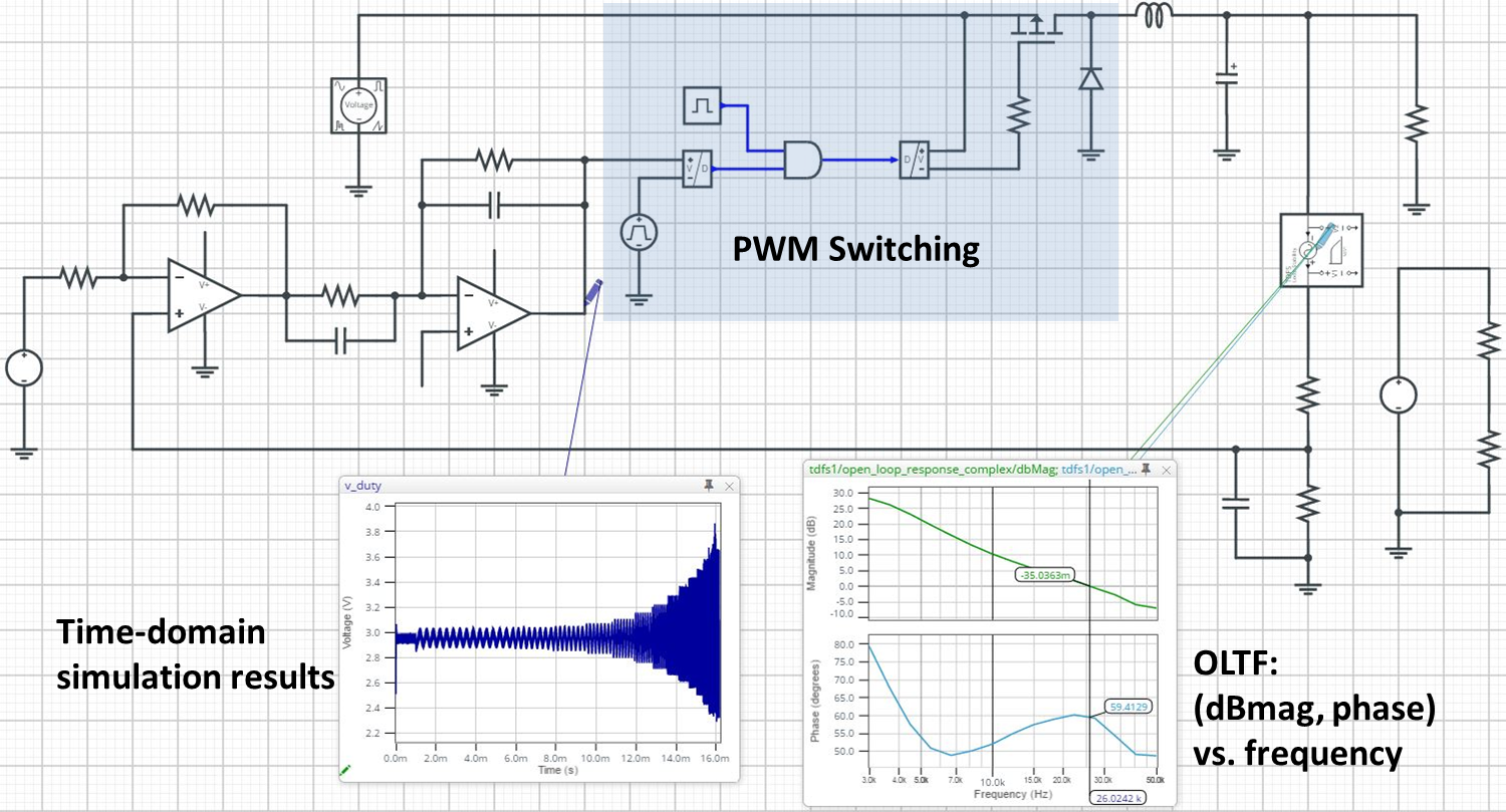
The first example circuit demonstrates a TDFS Loop Stability measurement for a “buck” or step-down DC/DC switching power converter. There is no need for a “state-average” or continuous equivalent model of the PWM section of the design, as is normally used for "AC" analysis. Rather, the actual switching circuit component models (Power MOSFET, Diode, modulator ramp function, etc.) can be used directly.
This converter is operating at 200 kHz, and is converting a 12V DC input to a regulated 5V output, while supplying a 5A current to the 1 Ohm load resistor. The TDFS measurement shows the open-loop gain crossover frequency is at 26 kHz (green waveform), and the phase margin is approximately 60 degrees (light blue waveform). This verifies that the op-amp based lead-lag compensator is providing adequate stability margin for this load condition.
(Note: You can click on the link or the image and it will open a “live” version of this design in your browser. You can interact with the design (e.g. move waveform probes around) or make a copy of it, change as desired and then run new simulations. This is currently not available on mobile devices).
The TDFS measurement set-up is similar to that described in Part 1 of this Blog Series. The frequency range (3 kHz to 50 kHz) and number of points (15) were specified, and the sinusoidal stimulus amplitude was set to 0.5 V. This was to allow adequate signal level above the switching noise of the circuit, but well within the “linear” operating region of the circuit. This is verified by examining the actual time domain signals at various points in the circuit. For example, the op-amp output (dark blue waveform) confirms that the op-amp is operating well within the 0 to 5 V rail limits over the entire frequency sweep range. Note also that no “DC bias” is needed for the injected stimulus signal, as was the used in Part 1 for direct TDFS gain/phase measurements. This is because the closed-loop operation provides its own bias at the desired operating point.
TDFS Open-Loop Frequency Response for PMSM/SVM Motion Control System
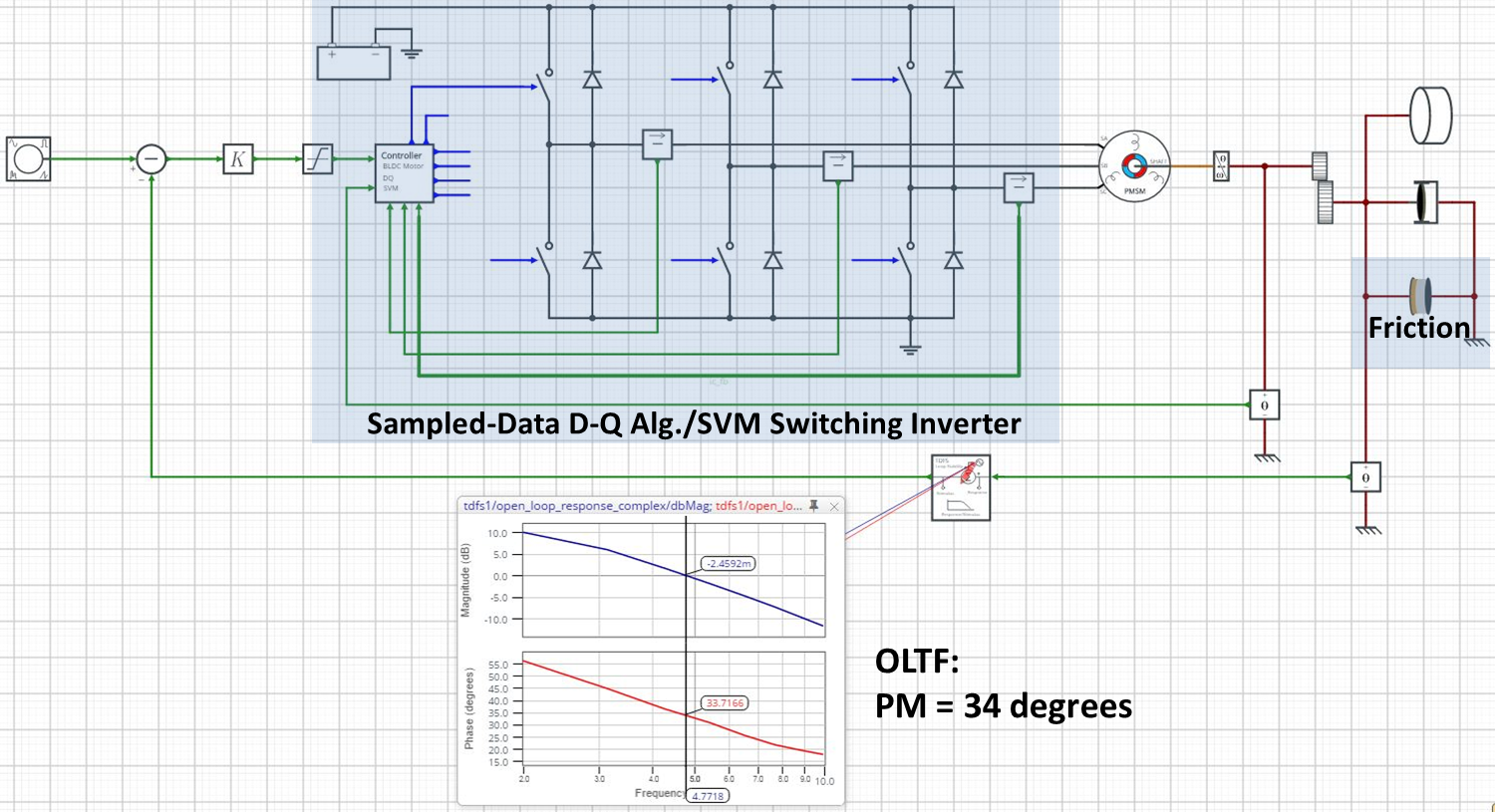
The second example is a closed-loop motion control system. The motor is a permanent magnet synchronous machine (PMSM), driven by a space-vector modulated (SVM) switching inverter and controlled by a sampled-data D-Q algorithm. Even the load includes a non-linear stick-slip friction characteristic. Each one of these system features would prevent traditional “AC” or frequency-domain stability assessment from being performed.
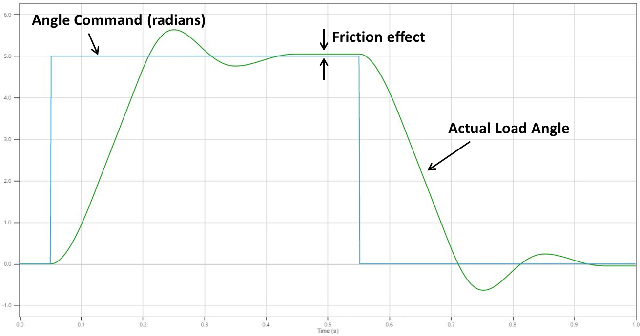
The TDFS Loop Stability measurement results are shown in the waveform viewer. The open-loop gain (dBMag, blue) and phase (red) show that the unity gain crossover frequency is just below 5 Hz, and the phase margin is just under 34 degrees. This is consistent with the overshoot/ringing of the step response, observed in the simulation results for the companion example: "Motion Control System with PMSM and SVM Drive - Step Response", and as shown in the figure below. Note that the step response is not quite the same that expected for a linear system. For example, there is steady-state error after settling, due to the static friction in the load.
More to this Series!
In Parts 1 and 3 of this blog series, I discuss other TDFS measurement capabilities and models that are provided in PartQuest Explore. In Part 1, I show the most basic use of TDFS, for simple open-loop transfer function (i.e. gain and phase) measurements of switched capacitor and mixed-signal filter circuits. In Part 3, I demonstrate the ability to measure the input impedance vs. frequency for a switching power converter, and determine the impedance stability of a distributed power system, where long cables (i.e. transmission line!) can have a significant destabilizing impact.
* D. Venable, “Testing Power Sources for Stability”, Venable technical paper #1, Venable Industries.
- 413 views


