Interactive Tunable Designs
PID Control
Did you ever wish you could just play with a PID control loop, to try "tuning" those P, I and D gains to see what they do? You're in luck!
This is a "virtual" motor speed control loop, just waiting for you to take it for spin! Go ahead and try out this schematic in our editor. This is a "live" and interactive design.
This design is "Live:" change any parameter (in blue) and run a simulation to see the results.
You can double-click on any of the PID blocks (Proportional, Integral or Derivative), change its value, then click the green "Play" arrow to run a new simulation and see the updated results. For example, try changing the derivative gain Kd from 1.1m to 0.5m and watch what happens to the system step response... congratulations, you’ve made an oscillator!
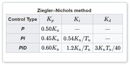
The initial gain calibrations were made for this design using the classic "Ziegler-Nichols" tuning method. In this method, the Ki and Kd gains are first set to 0.0. Then the Kp gain is increased until the system is just marginally stable... level oscillations not growing or decaying. That Kp gain value is defined as "Ku", and the period of oscillation is measured and defined as "Tu". Then the following table gives the recommended values for Kp, Ki and Kd.
You can try other settings, to see if you can improve on the performance given by the Ziegler-Nichols values (e.g. lower overshoot, faster settling, etc.)

Image courtesy Wikipedia:
https://en.wikipedia.org/wiki/PID_controller
You can go deeper into practical PID Control design, such as the effects of limited drive voltage and losses in power electronics devices. And PID Control is just one example.