
by Mike Donnelly
21 May 2024

In a companion article published on RS-DesignSpark, I described how a fuel injector driver can leverage the voltage clamping behavior of avalanche-rated power MOSFETs, to improve the speed or “crispness” at injector turn-off. In this article, I’ll show how a simple open-loop voltage doubler circuit can improve the turn-on performance.
The first step is to determine the sensitivity of the fuel injector solenoid response time to the applied voltage. The interactive test circuit shown in Figure 1 clearly illustrates that relationship. A 3A current step command is given to an ideal driver at the beginning of the simulation. The applied voltage is limited to the specified battery voltage, which is being swept from 12V to 48V in 4V increments. The blue waveforms show the solenoid current initial ramp up, where di/dt is limited by the solenoid inductance at each voltage level (V = L*di/dt). The orange waveforms show the corresponding solenoid armature position change, or "pull-in" response, for those voltage levels. Note that this includes the "bounce" as it impacts the hard-stop at the end of its stroke, which depends on the mechanical properties of the injector.
Figure 1: Calibration test: The effect of drive voltage on injector response
If you plot the solenoid current waveforms in the main viewer (right-click, “Plot in Viewer”) and then use the "LevelCross" measurement option set to 2.95A, you’ll see the time delay for the current to reach the desired “pull-in” setpoint (~3A), plotted as a function of the supply voltage. This can be seen in Figure 2.
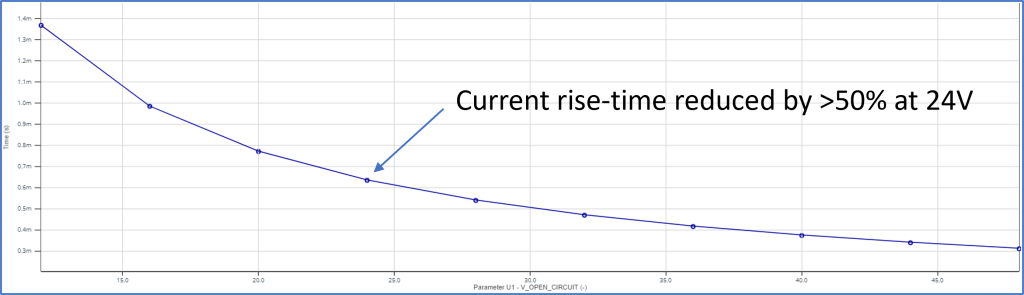 |
Figure 2: Injector current rise time (from 0 to 3A) vs. supply voltage
Note that most of the current risetime performance improvement is gained by raising the supply voltage from 12V to 24V. Above that level there is diminishing returns for speeding up the current rise. This indicates that a simple voltage doubler may be sufficient to improve injector turn-on responsiveness, eliminating the cost and complexity of a closed-loop boost converter.
As seen in the upper left of the schematic in Figure 3, a voltage doubler circuit is used to improve the turn-on response of the fuel injector. The Nexperia BUK9M85-60E Power MOSFETs M3 and M4 are rapidly and alternately switched on and off. When M4 is ON, the low side of C1 is pulled to ground and the battery charges C1 via diode d2 and inductor L1. When M4 is turned OFF and M3 is turned ON, the low side of C1 is raised up to the battery voltage level, so that current flows from the high side of C1, via L1 and diode d2, to charge the output capacitor C2. Depending on the load current, this process can raise the output voltage up to approximately 2x the battery voltage. Note that this is simple open loop operation, no voltage feedback mechanism is used to regulate the output voltage.
Figure 3: Complete fuel injector driver with Quick ON and OFF
Since this is a "Live, Interactive" design, you can simply double-click on the blue-highlighted battery and change its open circuit voltage to any value within the range of 7V to 24V. Then you can run a new simulation (click the large green arrow) to see the effect of that change. Operating at 7V simulates cranking/engine-start conditions, where the voltage doubler helps maintain adequate injector performance. And because we are using 60V rated MOSFETs for all the switches, this same circuit can be used in a 24V system, doubling that voltage is not a problem.
The Fuel The Fuel Injector “Fire Control” block provides the necessary logic to coordinate the main injector drive MOSFETs (M1 and M2) that regulate the solenoid current to the user specified “pull-in” and “hold” levels. It also provides control for the voltage doubler function, as described above. This control logic could be implemented within the engine controller. This would support the requirement of the voltage doubler circuit to be given a small lead time (approximately 1ms) to begin charging C2, before the actual injector fire event. It would also support limiting the duration of voltage doubler operation, which can be turned off for efficiency after the pull-in solenoid current level is reached.
If this system’s performance does not meet your application needs, you can click the orange-yellow button labeled “Edit in PartQuest Explore”. You’ll then be able to save a copy and edit it to implement your own circuit/system design.