
by Mike Donnelly
1 March 2021
The Simcenter Flotherm team recently released a new capability that I believe will revolutionize the electro-thermal design process! It is called BCI ROM (Boundary Condition Independent – Reduced Order Model) technology, a modeling approach to capture accurate thermal characteristics from analysis of the 3D physical system, ready for use in 1D circuit simulation.
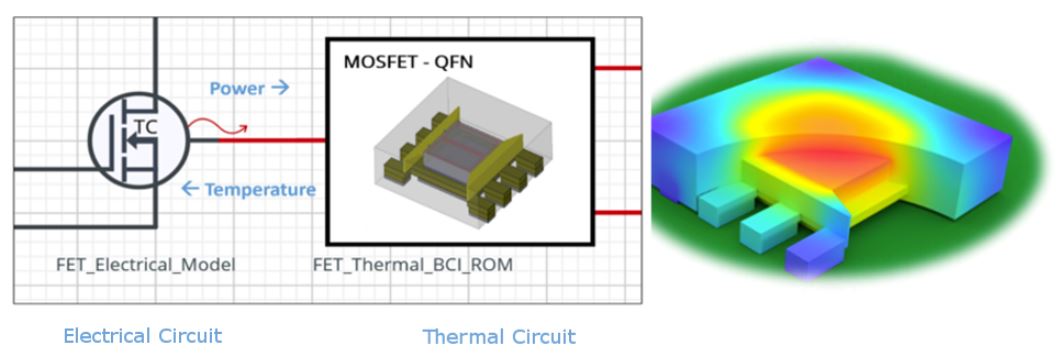
My colleague Byron Blackmore has written a great article on this topic: “The future of thermal design – earlier electrothermal analysis”. This method is applicable to both components and entire PCB/enclosure systems. These generated BCI ROM models can be connected together in a thermal “circuit” or schematic, with an inherent heat-flow conservation principle governing their interaction, in the same way KCL underpins electronic circuit simulation.
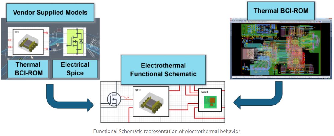
This technology will help electronics designers facing major thermal challenges due to the incessant demand for smaller/lighter/cheaper/faster/more-features, all of which increase the problem of getting the heat out! BCI ROM is the lynch-pin technology that supports a supply chain for thermal models, just like the existing one for functional electronics models (SPICE, VHDL-AMS, IBIS, etc.). It enables Component Manufacturers and OEM Electronics and Thermal Engineers to work more effectively together to solve difficult electro-thermal design problems.
The generated BCI ROM models are in IEEE Standard VHDL-AMS format. They leverage the language’s capability to express the simultaneous differential equations needed to represent the dynamic thermal characteristics. These equations are conveniently expressed in compact matrix-math form. Also, the TextIO feature of VHDL-AMS is leveraged, to keep the large set of model data separate from these governing equations. These two features greatly improve model readability.
Updated Example: Digital Smartphone
In a previous article, "Electro-Thermal Design Part 1: Digital Electronics", I showed a “smartphone” application example. It demonstrated how electro-thermal simulation could be used to design a Dynamic Thermal Management (DTM) system. That example has been updated to include the new BCI ROM modeling approach, as shown in this “Live – Tunable” design:
The components modeled are primarily digital ICs, and only their electrical power consumption and heat transfer to the package and board/enclosure is modeled. The power input at each operating state (idle, streaming and gaming) is specified by the user, along with the corresponding calibration voltage and clock rate.
The "thermals" of the board/enclosure and the packages of the processor and memory components, are represented by IEEE Standard VHDL-AMS BCI-ROM models generated by Simcenter Flotherm. These generated models were directly and easily imported into this electro-thermal schematic, so that they could be simulated in this functional system context.

This design can be used during the development process of the DTM "maximum clock-rate algorithm", shown on the far left of the schematic. The sampled-data algorithm is attempting to keep the temperature of the phone, as measured by a thermistor placed at the "temp_above_processor" temperature sense point, between two limiting values. It does this by adjusting the global clock rate that is distributed to all the digital components.
“Tune” the Smartphone design to meet your specifications
You can make changes to any of the component parameters shown in blue, and run new simulations to see the effect of those changes. For example, try changing the temperature sample_period on the control algorithm from 20 to 60 seconds. Note that the clock rate no longer drops to 2 GHz while "gaming". This is because the extra sampling delay gives the temperature transient more time to fall below the upper limit, after the clock-rate is decreased from 8 GHz to 4 GHz. Now see what happens if you block the heat flow path from the top of the processor to the phone case (i.e. add insulation instead of the good heat conductor). You can do this by changing the RTH_Top from 0.2 to 50 degC/Watt. This of course interferes with the temperature feedback path which is critical to this DTM approach. Notice how much hotter the CPU, GPU and Connectivity temperatures become.
Updated Example: LED Spotlight
In another previous article, "Electro-Thermal Design Part 2: Analog Electronics", I discussed an “LED Spotlight” application example. It also showed how electro-thermal simulation could be used to design an over-temperature protection system. That example has also been updated to include BCI ROMs:
In this design, a Vishay NTCLE100 Thermistor is used in a detection circuit to monitor the enclosure temperature. It is used to trigger thermal shut-down, to keep the temperature of the spotlight's Nylon 6 polymer lens well below "Tg" (glass transition temperature). This is particularly helpful when operating at higher external ambient temperatures.
The thermal side of the circuit consists of connected BCI-ROMs, also generated by Simcenter Flotherm in the IEEE Standard VHDL-AMS format. Thermal BCI-ROMs for the linear regulator, three LEDs, and the current sense resistor packages are connected to the corresponding electrical models of these devices, where heat-flow and temperature information is exchanged. The thermal environment is represented by a BCI-ROM of the rest of the system: PCB, lamp casing, and the thermistor.
“Tune” the LED Spotlight design to meet your specifications
You can make changes to any of the component parameters shown in blue, and run new simulations to see the effect of those changes. For example, increasing the battery voltage will cause more power dissipation in the linear regulator, and therefore faster temperature rise. Increasing r_isense reduces the LED current and corresponding power dissipation of the LEDs and the linear regulator.