Application Area

Boost MPPT NIT

Jonokuchi
Designer
Jonokuchi
Member for
6 years 1 monthAdd a bio to your profile to share information about yourself with other SystemVision users.
upgraded Controlled Buck-Boost Power Converter

ClaudioAlarcn
Designer
ClaudioAlarcn
Member for
8 years 5 monthsAdd a bio to your profile to share information about yourself with other SystemVision users.
PID Tuning with Controlled Power Boost converter
ClaudioAlarcn
Designer
ClaudioAlarcn
Member for
8 years 5 monthsAdd a bio to your profile to share information about yourself with other SystemVision users.
Controlled Buck-Boost Power Converter
ClaudioAlarcn
Designer
ClaudioAlarcn
Member for
8 years 5 monthsAdd a bio to your profile to share information about yourself with other SystemVision users.
Controlled Power Boost converter
ClaudioAlarcn
Designer
ClaudioAlarcn
Member for
8 years 5 monthsAdd a bio to your profile to share information about yourself with other SystemVision users.
Automotive Start-Stop … Keep the lights ON!
by Mike Donnelly
13 June 2016
![]()
You’ve probably noticed when you start your car that some of the optional electronics turn off, such as the radio and some LED lighting circuits. That’s because the high current draw of the starter motor pulls the system voltage far below the normal 12+ volt operating level. Critical circuits are designed to operate at these low voltages … if the ignition circuit didn’t work, you would be cranking for a very long time! But many functions are not designed for that low-voltage condition. After all, it’s a once-per-trip occurrence, and drivers expect the drop-out behavior.
But for new vehicles with “Start-Stop” operating mode, the engine (ICE) is turned off frequently during idle periods to improve fuel economy. These same low-voltage drop-outs must be avoided during re-start. The radio must play on, even in heavy traffic!
The ON Semiconductor® NCV8876 is designed for this exact purpose. It is a current-mode boost converter controller, and it includes many integrated functions to reduce the complexity of the external circuit. A typical application circuit is shown in the PartQuest Explore schematic below:
The simulation results show the output to the fixed load resistor during battery drop-out and recovery. In this application, the output voltage (dark blue waveform) is maintained above 6.4V during the drop-out transient, and regulates at 6.8V during sustained low voltage (4V) battery operation (orange waveform).
Note: This schematic is “Live”, you can pan and zoom (like Google Maps), and you can move the waveform probes around and look at signals on any of the nets (i.e. “wires”) or within any of the components. You can also double click on components to see their parameter values. If you click "Edit in PartQuest Explore" button, you'll be able to save a copy and then change and re-simulate the circuit as you please.
This circuit also includes a soft-saturation inductor component from Coilcraft®. The load current for the XAL4030-332 inductor in this application is 4A during nominal 12V operation. But during boost operation, the current reaches 6.6A peak (light blue waveform). This could saturate a typical inductor if it were sized for the nominal load, resulting in a collapse of the effective inductance. But notice that the actual instantaneous inductance (green waveform) only drops to 2.2uH, for this nominal 3.3uH part.
If that 33% drop in inductance doesn’t sound small, the next example shows what can happen if a typical “non-soft-saturation” inductor carries current beyond its operating limits, even momentarily. Inductance collapse leads to large current spikes that can potentially damage other power electronics components. Fortunately in this case, the “hiccup-mode” overcurrent protection capabilities of the NCV8876 limit the magnitude of the current spikes to a level below the ratings of those other components.
The simulation results show that in this case, the boost output voltage (dark blue waveform) falls to approximately 5V instead of the proper boost set-point of 6.8V, when the battery voltage (orange waveform) drops to 6V. Because the NCV59302 Linear Regulator has a very low drop-out voltage, the current through the 2.3 Ohm load resistor is maintained at just under 2.2A throughout the entire operation.
While this load current level is within the rating limits of the inductor (2.3A RMS Max.), it is approaching the saturation inductance “cliff” for this non-soft-saturating part. So when the NCV8876 activates boost control, it switches on the Power MOSFET briefly, effectively grounding the low side of the inductor through the small current sense resistance (0.03 Ohms). If the nominal 3.3uH inductance value were maintained, this would result in a slow current build-up:
V/L = di/dt = 6V/3.3uH = 1.8A/us
But in fact the inductance collapses with further current increase, causing the di/dt value to become very large. The inductor current spikes to well over 10A (light blue waveform), and the corresponding inductance crashes to a small fraction of its nominal value (green waveform).
The current spikes could have gone much higher, possibly resulting in damage to the NVGS3130 Power MOSFET, which has a rated pulse current maximum of 19A. If you zoom in on the magenta waveform, you'll see the Ids current rising, slowly at first while the inductance is intact, but then rapidly rising to over 11A as the inductance collapses, all in just 100ns! Fortunately the gate voltage (brown waveform) is cut off to prevent further current rise. This is thanks to the overcurrent protection feature of the NCV8876. When an overcurrent condition is detected, the device immediately goes into “hiccup-mode”, in which the gate drive is turned off and remains off for a count of 1024 clock cycles. After the mandatory hiccup period, the NCV8876 reattempts boost operation, but with continued overcurrent monitoring. Note that the current spikes are repeated with just over a 2ms period, because the clock is programmed to just over 2 us period (450 kHz switching frequency) in this design.
Click here to learn more about the capabilities of the ON Semiconductor NCV8876.
Click here to learn more about soft-saturation inductor technology from Coilcraft.
The author would like to thank Robert Davis, Automotive Power Supply System Architect at ON Semiconductor, for his contributions to both creating the high-fidelity model of the NCV8876, as well as providing key design insight for Automotive Start-Stop Applications. The author would also like to thank Chris Hare, Technical Marketing Engineer at Coilcraft, for his help in developing inductor models with accurate saturation behavior.
- 168 views
Got Current Spikes? Soft-Saturation Inductors to the Rescue!
by Mike Donnelly
15 December 2015

Design requirements often focus on steady-state performance and operating conditions. Component sizing and ratings selection, if based solely on meeting these objectives, can lead to unexpected and sometimes catastrophic results. Parts may be most severely stressed during transients that occur infrequently, perhaps only once during the initial start-up!
Because they are infrequent, designers may spend less time thinking about transient conditions. After all, the marketable product features are the “normal operation” characteristics, such as being more “Green” (i.e. higher efficiency) or having better performance (e.g. faster, more accurate, lower noise, etc.). These design goals can overshadow the behavior during transient conditions, such as start-up, turn-off or load switching. But, infrequent does not mean “unlikely;” these conditions will happen!
Over-currents (or “spikes”) can occur during the start-up transient of a DC-to-DC power converter--not the expected current maximum that occurs during the initial overshoot, but the sharp increase in the inductor current ramping due to inductance “collapse.” This inductance drop occurs when the “expected” current overshoot exceeds the saturation point of the inductor’s magnetic core.
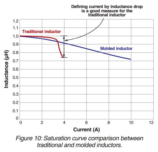
Coilcraft has provided an excellent article about the behavior of inductors and tools they provide to specify and compare performance among parts: http://www.coilcraft.com/pdfs/Doc1140_Beyond_the_data_sheet_Part1.pdf The image below is taken from that document. It shows Inductance vs. Current, and compares a traditional inductor (i.e. a coil wound around a ferrite core) vs. a “molded” or “soft-saturation” inductor (i.e. a core that is molded around the winding).
To demonstrate the implications of these “static” L vs. I curves in a dynamic or transient application, a comparison circuit was created. The circuit below shows is a simulation of the start-up transient for two nearly identical open-loop buck power stages (12V -> 3V). The only difference is that the top circuit uses an inductor model calibrated to a Coilcraft XAL6060-223 (22uH), which has "soft saturation" behavior. The bottom circuit uses a similarly sized inductor, a Coilcraft MSS1260-223, which has a more typical "hard saturation" characteristic.
The load resistor is 1 Ohm, so the nominal load current is 3 Amp. Both inductors work well for that steady-state operating condition. But during the turn-on transient, the current goes well above that nominal level, as the 110 uF output capacitor charges up. Notice in the top-center waveform plot that the inductor current reaches a peak of just over 7 Amps, whereas the bottom-center waveform plot shows the corresponding peak current exceeds 11 Amps in the traditional inductor! This may cause stress in the MOSFET and diode, which must switch this excessive current.
Note: This schematic is a “Live-Tunable” design, you can pan and zoom (like Google Maps), and you can move the waveform probes around and look at signals on any of the nets (i.e. “wires”) or within any of the components. You can also double click on components to see their parameter values. For the components highlighted in blue, you can change their parameter values and run a new simulation to see the effect of those changes. If you click the "Edit in PartQuest Explore" button, you'll be able to freely change any aspect of the design (e.g. delete or add new components) and re-simulate your own copy of this circuit.
The waveform plots on the left show the instantaneous inductance value of the inductor components. Note that the inductance of the traditional “hard-saturation” inductor collapses during the current overshoot, to just over 2 uH, or approximately 10% of its nominal value! The implication of the “inductance cliff” for the traditional inductor, shown in Figure 10, is this dynamic inductance collapse that results in the observed current spikes.
Note also that the actual inductance minimum for the soft-saturation inductor is approximately 14 uH. It maintains over 60% of its nominal inductance value throughout the current overshoot transient, and continues performing its primary function in the circuit.
While PartQuest Explore can certainly be used to simulate a circuit or system during normal operation and analyze its steady-state characteristics, the ability to predict behavior during transients can be even more valuable, because these aspects are generally outside the scope of standard design rules and analysis methods.
The author would like to thank Chris Hare of Coilcraft for his contribution not only to this article, but also for the soft-saturation models that are now included in the PartQuest Explore open-source library.
- 409 views